RFID-Controlled Access Gate
Automated Barrier System with Contactless RFID Authentication
The Problem I Wanted to Solve
How can we create an automated gate that only opens for authorized users? Modern access control systems use RFID (Radio-Frequency Identification) technology to identify users without physical keys or manual operation. This project combines RFID authentication with automated gate control—when an authorized card is scanned, the barrier opens; unauthorized cards are denied access and the gate remains closed.
Inspiration: Filipino RFID Toll Gates
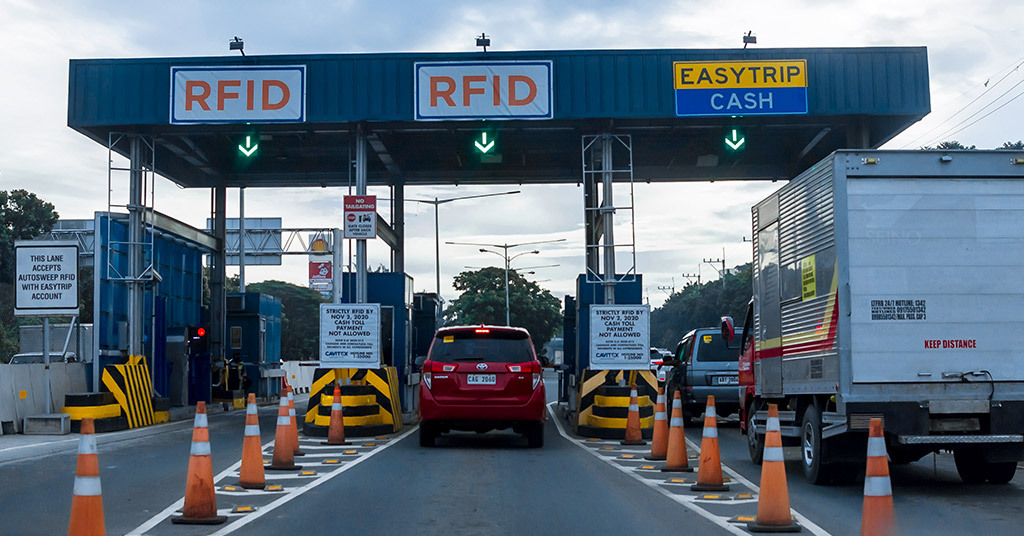
During our family travels to the Philippines, I observed RFID-enabled toll gates in action. Vehicles with registered RFID tags approach dedicated EasyTrip lanes, the system reads their tag through the windshield, verifies authorization, and automatically raises the barrier—all without the driver needing to stop or touch anything. This seamless combination of identification and automation fascinated me. I wanted to recreate this technology on a smaller scale to understand how RFID authentication controls physical access.
How the System Works
My RFID access gate provides secure, contactless entry control:
- RFID Card/Tag Scanning: Reads unique ID from RFID cards or key fobs when presented to reader
- Authorization Check: Arduino compares scanned ID against authorized card ID stored in code
- Gate Opens for Authorized Access: Servo motor lifts barrier arm to 90° when authorized RFID tag is detected
- Gate Stays Closed for Denied Access: Barrier remains at 0° (closed) when unauthorized tag is scanned
- Visual Feedback: Green LED (pin A0) lights up for authorized access, red LED (pin A1) for denied
- Audio Confirmation: Buzzer (pin A2) plays 1kHz success tone for 0.5s when granting access, 200Hz error buzz for 1s when denying
- LCD Display Messages: 16x2 LCD shows "Access Granted!" for authorized users or "Access Denied!" with card ID for unauthorized
- Automatic Closing: After authorized user passes through, gate closes automatically after 3 seconds
System Demonstration
Watch the RFID access gate in operation, demonstrating the final integrated system and step-by-step access cycles:
Final Demo: Complete System
Final demonstration of the fully integrated RFID gate system in operation
Demo Video 1: Authorized Access
Demonstration showing RFID card scan, authorization check, and servo-controlled gate opening for authorized access
Demo Video 2: Complete Access Cycle
Full cycle demonstration including LCD messages, LED indicators, buzzer feedback, and automatic gate closing after authorized entry
The Build Journey
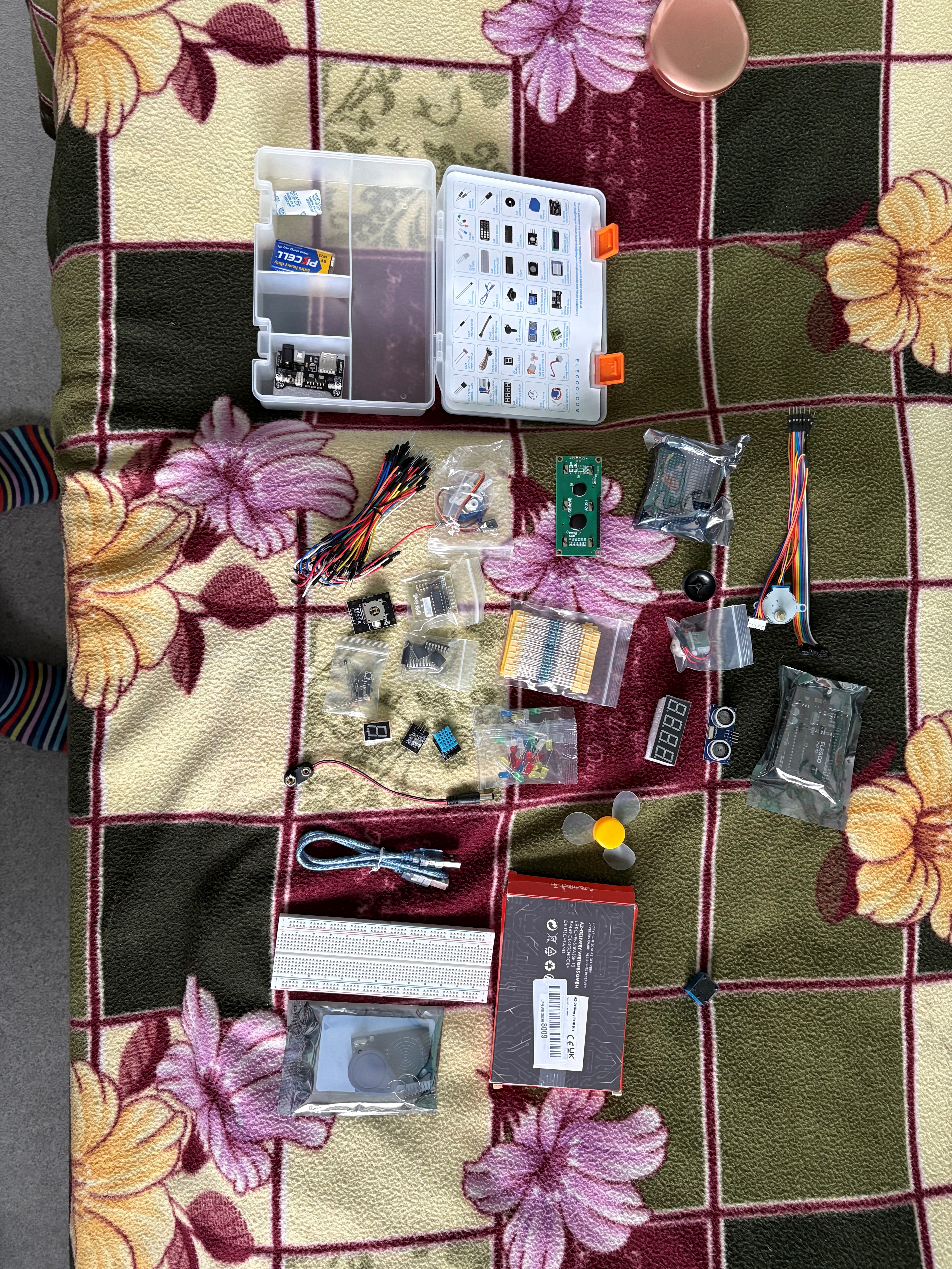
Step 1: Component Selection & Planning
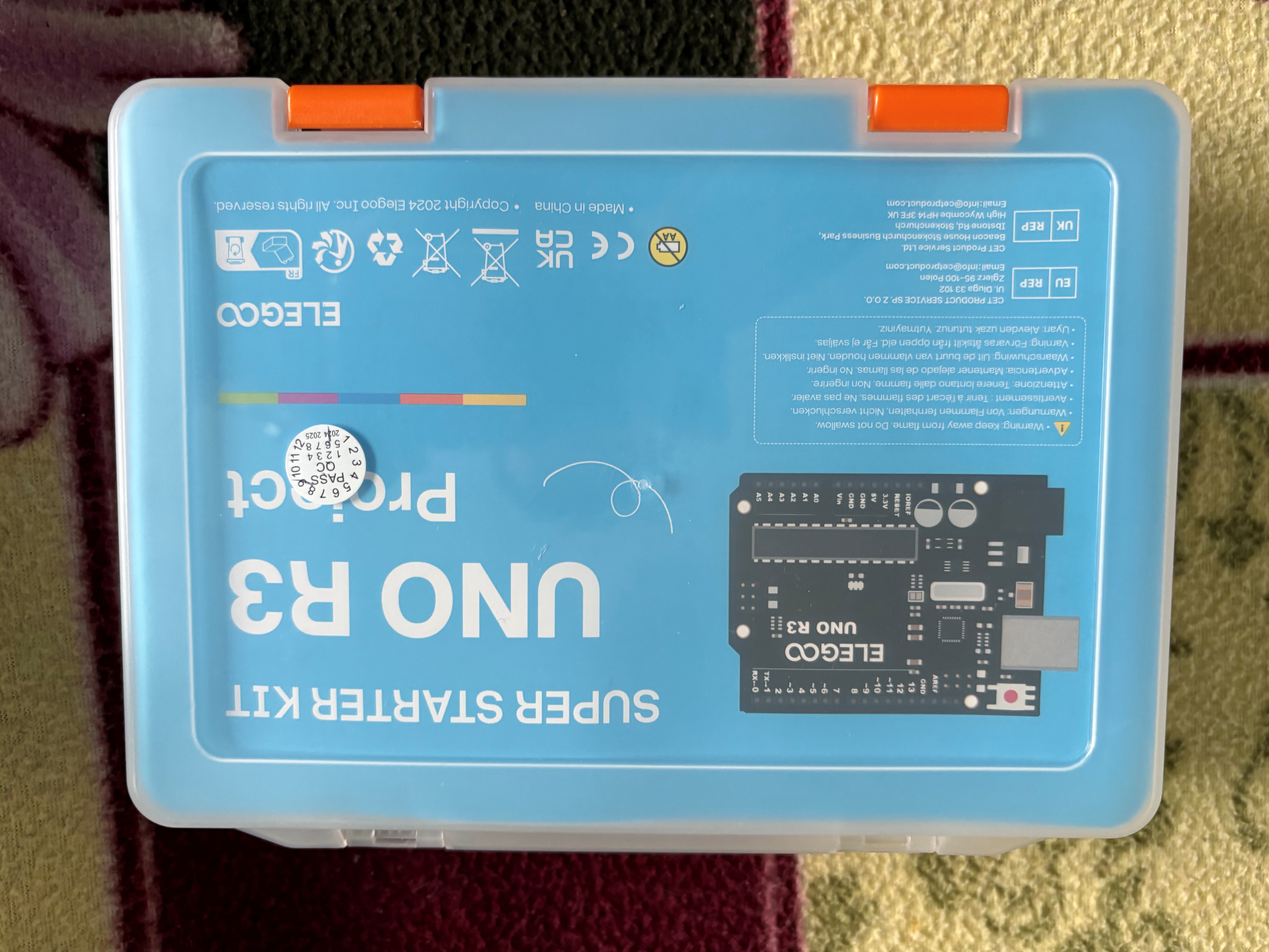
I started with the ELEGOO UNO R3 Super Starter Kit, which provided most components needed for this project. The kit includes Arduino board, breadboard, jumper wires, LEDs, resistors, buzzer, and servo motor. I purchased the RFID reader module (RC522) separately since it's not included in standard Arduino kits.
- Arduino Uno R3: Microcontroller brain—processes RFID data and controls all outputs
- RC522 RFID Reader Module: Reads 13.56MHz RFID cards/tags using Near Field Communication (NFC)
- SG90 Servo Motor: Controls gate barrier arm with precise 0-180° movement (connected to pin 6)
- 16x2 LCD Display (Parallel Mode): Shows real-time status messages (RS to pin 7, E to pin 8, D4-D7 to pins 2-5)
- LEDs (Red & Green): Instant visual feedback—green (pin A0) = access granted, red (pin A1) = denied
- Active Buzzer: Audio feedback (pin A2) with different tones for success/failure
- RFID Cards/Tags: Each has unique ID—my card ID "D2979DAB" programmed as authorized
- Breadboard: Allows testing circuit without permanent soldering
- Jumper Wires: Connect all components together
- 220Ω Resistors: Protect LEDs from excess current
System Logic Design: I mapped out the program flow: Continuously scan for RFID cards → When card detected, read its unique ID → Compare ID to authorized card ("D2979DAB") stored in code → If match found: rotate servo to 90° (open) + green LED + 1kHz beep (0.5s) + "Access Granted!" on LCD + wait 3 seconds + close gate to 0° → If no match: red LED + 200Hz buzz (1s) + "Access Denied!" with card ID on LCD + gate stays closed at 0°.
Step 2: Breadboard Circuit Assembly
Building the circuit on a breadboard allowed me to test connections before permanent soldering. The RFID module uses SPI (Serial Peripheral Interface) communication protocol, requiring specific Arduino pins: MOSI (pin 11), MISO (pin 12), SCK (pin 13), SS (pin 10), and RST (pin 9). I used colorful jumper wires to keep track of different signal types—red for power (5V), black for ground, and various colors for data signals.
- RFID Module (RC522): RST to pin 9, SS to pin 10, MOSI to pin 11, MISO to pin 12, SCK to pin 13, plus 3.3V power and ground
- Servo Motor: Signal wire to pin 6, powered from 5V with common ground
- LCD Display (Parallel): RS to pin 7, Enable to pin 8, D4 to pin 2, D5 to pin 3, D6 to pin 4, D7 to pin 5, plus 5V and ground
- Green LED: Pin A0 through 220Ω resistor to ground
- Red LED: Pin A1 through 220Ω resistor to ground
- Buzzer: Pin A2 to ground
The breadboard's organized layout made troubleshooting much easier when connections didn't work initially.
Step 3: Arduino Programming
I programmed the Arduino in C++ using the Arduino IDE. The code requires several libraries: MFRC522 for RFID communication, Servo for motor control, LiquidCrystal for the display (in parallel mode), and SPI for communication.
#include <LiquidCrystal.h>
#include <SPI.h>
#include <MFRC522.h>
#include <Servo.h>

// Pin Definitions
#define RST_PIN 9          // RFID reset pin
#define SS_PIN 10          // RFID slave select
#define SERVO_PIN 6        // Servo motor control
#define GREEN_LED A0       // Access granted indicator
#define RED_LED A1         // Access denied indicator
#define BUZZER A2          // Audio feedback

// Initialize components
LiquidCrystal lcd(7, 8, 2, 3, 4, 5);  // LCD in parallel mode
MFRC522 rfid(SS_PIN, RST_PIN);         // RFID reader
Servo doorServo;                        // Servo for gate

// Authorized card UID (unique to my card)
String authorizedCard = "D2979DAB";

void setup() {
  // Initialize LCD display
  lcd.begin(16, 2);

  // Initialize RFID reader
  SPI.begin();
  rfid.PCD_Init();

  // Initialize servo (start at closed position)
  doorServo.attach(SERVO_PIN);
  doorServo.write(0);  // 0° = gate closed

  // Configure LED and buzzer pins
  pinMode(GREEN_LED, OUTPUT);
  pinMode(RED_LED, OUTPUT);
  pinMode(BUZZER, OUTPUT);

  // Display ready message
  lcd.print("RFID Ready!");
  lcd.setCursor(0, 1);
  lcd.print("Scan a card...");
}

void loop() {
  // Check if card is present and read it
  if (rfid.PICC_IsNewCardPresent() && rfid.PICC_ReadCardSerial()) {

    // Read card UID and convert to string
    String cardID = "";
    for (byte i = 0; i < rfid.uid.size; i++) {
      // Add leading zero if byte is less than 0x10
      cardID += (rfid.uid.uidByte[i] < 0x10 ? "0" : "");
      // Convert byte to hexadecimal string
      cardID += String(rfid.uid.uidByte[i], HEX);
    }

    // Clear LCD and check authorization
    lcd.clear();

    if (cardID.equalsIgnoreCase(authorizedCard)) {
      // AUTHORIZED ACCESS
      lcd.print("Access Granted!");
      digitalWrite(GREEN_LED, HIGH);
      tone(BUZZER, 1000, 500);    // 1kHz success beep for 0.5s
      doorServo.write(90);         // Open gate (90°)
      delay(3000);                 // Wait 3 seconds for entry
      doorServo.write(0);          // Close gate
      digitalWrite(GREEN_LED, LOW);

    } else {
      // UNAUTHORIZED ACCESS
      lcd.print("Access Denied!");
      lcd.setCursor(0, 1);
      lcd.print("ID: " + cardID);  // Show scanned card ID
      digitalWrite(RED_LED, HIGH);
      tone(BUZZER, 200, 1000);     // 200Hz error buzz for 1s
      delay(3000);
      digitalWrite(RED_LED, LOW);
    }

    // Reset to ready state
    delay(500);
    lcd.clear();
    lcd.print("RFID Ready!");
    lcd.setCursor(0, 1);
    lcd.print("Scan a card...");

    // Halt RFID card to prevent multiple reads
    rfid.PICC_HaltA();
  }
}- UID Reading: RFID cards store unique IDs as byte arrays. The code loops through each byte, converts to hexadecimal format, and builds a complete ID string.
- String Comparison: Uses equalsIgnoreCase() to match scanned ID against stored authorized card "D2979DAB", ignoring uppercase/lowercase differences.
- Tone Generation: tone(pin, frequency, duration) creates different sounds—1000Hz high beep (500ms) signals success, 200Hz low buzz (1000ms) signals error.
- LCD Control: lcd.clear() clears display, lcd.setCursor(col, row) positions text, lcd.print() displays messages.
- Servo Positioning: write(0) closes gate horizontally, write(90) opens gate vertically to 90-degree angle.
- Card Halt: rfid.PICC_HaltA() prevents same card from being read multiple times rapidly (debouncing).
Step 4: LCD Display Testing
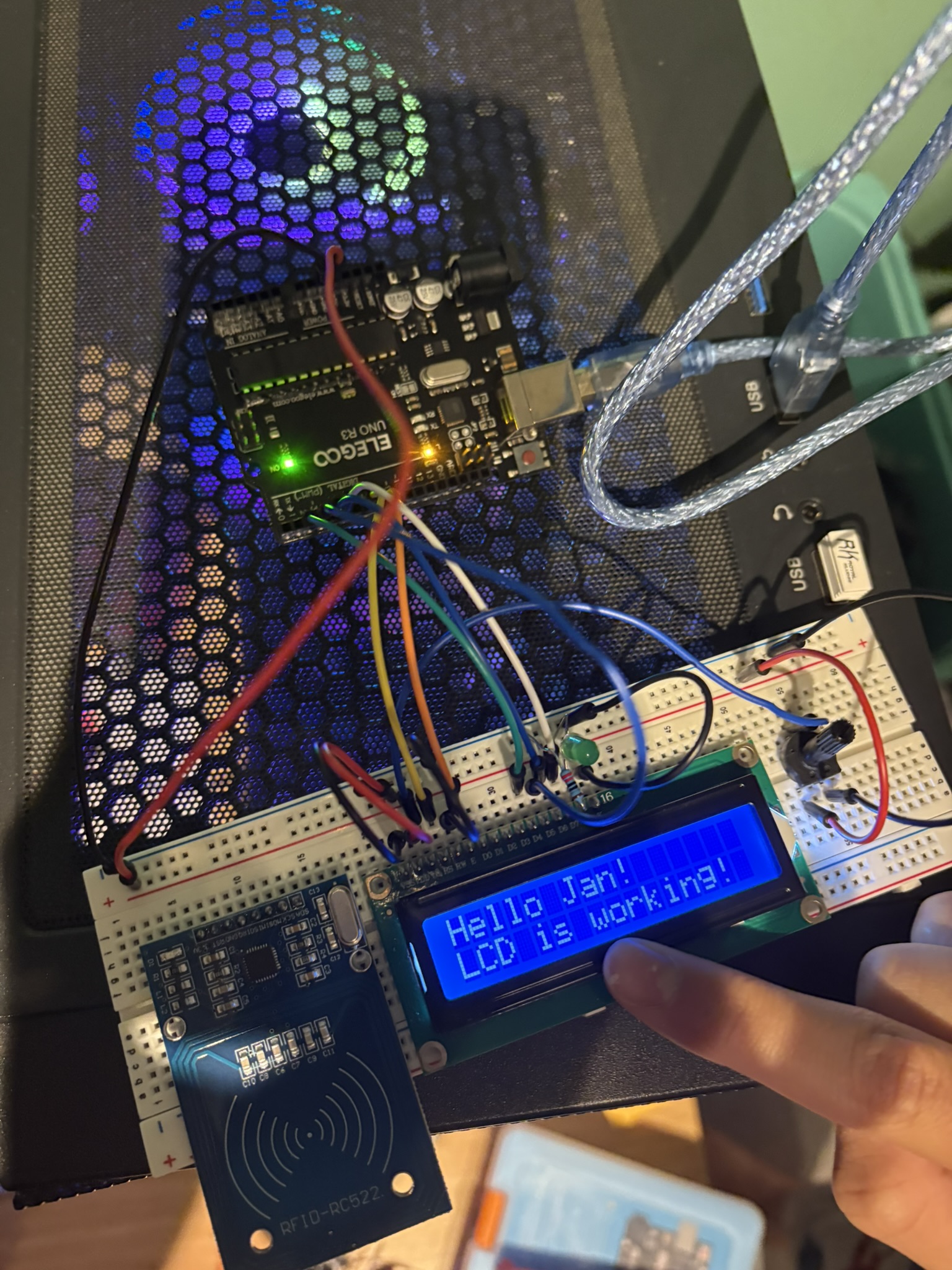
Before integrating everything, I tested each component individually. The LCD display was particularly important since it provides user feedback. The display uses parallel mode (6 data pins) rather than I2C (2 pins), which requires more Arduino pins but provides faster updates.
The test message confirmed the display was communicating properly with the Arduino. I verified all pin connections: RS (pin 7), Enable (pin 8), and data pins D4-D7 (pins 2-5) were correctly wired.
Step 5: Full System Integration
With all individual components tested, I integrated everything into one complete system. This phase involved ensuring all components work together without conflicts—particularly important since the RFID module, servo motor, and LCD all need to function simultaneously.
- Power Management: Servo motor draws significant current when moving. I ensured the servo was powered directly from the 5V pin with common ground to prevent Arduino voltage drops that could cause resets.
- Pin Allocation: Careful planning was needed—RFID uses hardware SPI pins (10-13), LCD uses 6 pins (2-8), servo uses pin 6, and LEDs/buzzer use analog pins A0-A2 to avoid conflicts.
- Timing Coordination: LCD updates, LED changes, buzzer tones, and servo movement all need precise timing. Used delay() for blocking delays and tone() with duration parameter for non-blocking sound.
- RFID Reading Reliability: The PICC_HaltA() command ensures the system doesn't repeatedly read the same card when held near the reader, preventing multiple rapid trigger events.
- Gate Position Calibration: Tested servo angles—0° keeps barrier horizontal (closed), 90° raises it vertical (open). Physical barrier arm attached to servo horn in correct orientation.
You can see in this photo the system is operational—multiple colored wires indicate the complex connections between all components. The organized layout on the breadboard made it easy to trace connections when troubleshooting issues.
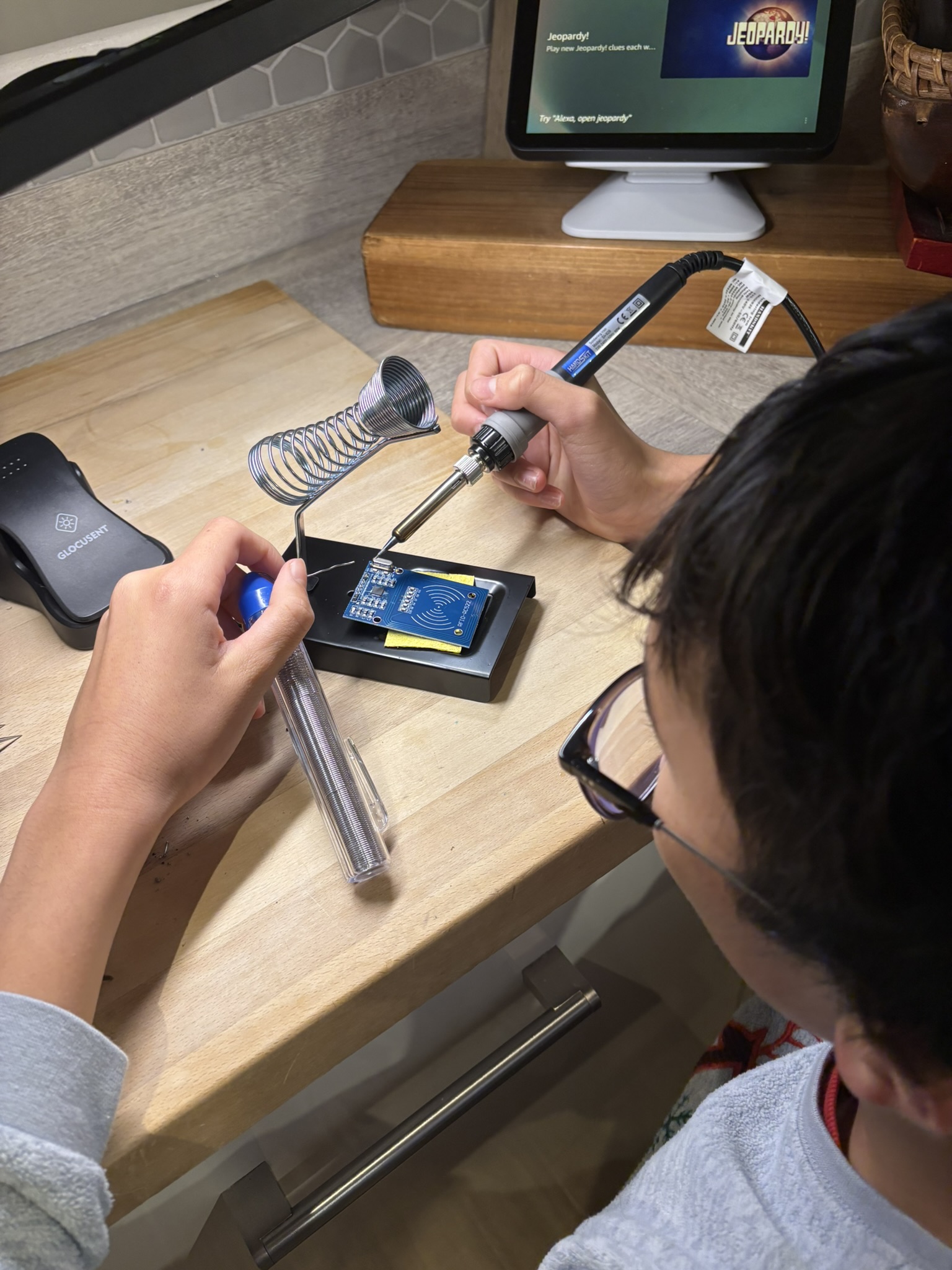
Step 6: Permanent Soldering & Assembly
RFID Tag Testing & Component Detail
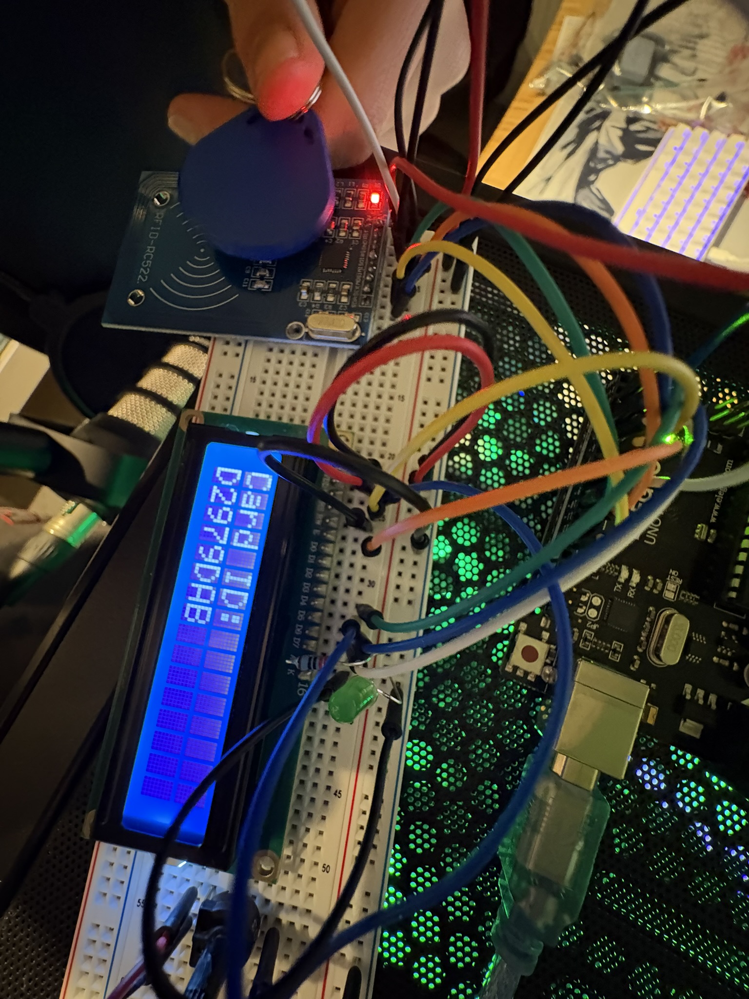
This close-up shows the RFID reader module (RC522) and one of the blue RFID key fobs. Each tag contains a tiny chip and antenna coil that responds when energized by the reader's electromagnetic field. The reader and tag don't need to touch—they communicate wirelessly when within a few centimeters.
I tested multiple RFID cards and fobs to ensure the system could distinguish between them. Each has a unique identifier programmed by the manufacturer. In my code, I stored my specific card ID "D2979DAB" as the only authorized card. Any other ID would be rejected and displayed on the LCD. This mimics real-world access control where only registered employees can enter secure areas.
Once the breadboard prototype worked reliably, I began creating permanent connections through soldering. Soldering creates much more secure electrical connections than breadboard jumper wires, which can become loose over time.
This photo shows me soldering header pins to the RFID reader module. The "helping hands" tool holds the component steady while I apply the soldering iron and solder. Each joint must be heated properly to create a strong, conductive connection—too little heat and the solder won't flow properly; too much heat can damage components.
Watch me soldering connections for the RFID access gate system
Soldering Safety & Technique: I learned proper soldering practices—work in well-ventilated area, never touch the hot iron tip (300-400°C), use helping hands or vice to hold components, apply solder to the heated joint (not directly to the iron), and inspect each joint for good coverage and no cold solder joints.
The Technology Behind It
RFID Technology (Radio-Frequency Identification)
RFID uses electromagnetic fields to automatically identify and track tags. The system consists of two parts:
1. RFID Reader (RC522 Module): Generates a 13.56MHz electromagnetic field through its antenna coil. When powered, this field continuously surrounds the reader waiting for a tag to enter range.
2. RFID Tags (Cards/Key Fobs): Each contains a microchip and antenna coil. When a tag enters the reader's electromagnetic field, the field energizes the tag's coil (inductively powering it), and the tag's chip transmits its unique ID back to the reader. This all happens wirelessly within milliseconds.
- Reader continuously broadcasts 13.56MHz electromagnetic field
- Tag enters field range (within approximately 5cm)
- Tag's coil harvests energy from the field (no battery needed)
- Tag powers up and transmits its stored UID (Unique Identifier)
- Reader receives and decodes UID
- Arduino processes UID and makes access decision
This is called "passive RFID" because tags don't need batteries—they're powered by the reader's field.
Servo Motor Control
The servo motor acts as the gate barrier mechanism. Unlike regular motors that spin continuously, servo motors can move to and hold specific angles—perfect for a gate that needs to be either fully closed (0°) or fully open (90°).
How Servo Positioning Works: The Arduino sends PWM (Pulse Width Modulation) signals to the servo. The width of each pulse tells the servo what angle to move to:
- 1.0ms pulse: 0° position (gate closed/horizontal)
- 1.5ms pulse: 90° position (gate open/vertical)
- 2.0ms pulse: 180° position (maximum rotation)
My code uses servo.write(0) to close the gate and servo.write(90) to open it. The Arduino Servo library handles all the complex PWM timing automatically.
LCD Display Communication
This project uses a standard 16x2 LCD in parallel mode, which requires 6 data/control pins from the Arduino. While parallel mode uses more pins than I2C (which only needs 2), it provides faster display updates and doesn't require additional I2C address configuration.
Pin Configuration:
- RS (Register Select) to Pin 7: Tells LCD whether data is a command or character
- Enable to Pin 8: Triggers LCD to read data on the bus
- D4-D7 to Pins 2-5: 4-bit data mode (sends data in two nibbles)
The LiquidCrystal library handles all the complex timing and signaling automatically. My code simply calls lcd.print() to display text and lcd.setCursor() to position it.
Arduino Program Logic
The Arduino acts as the system's brain, coordinating all components:
- INITIALIZE: Set up RFID reader (SPI communication), servo motor (start at 0°), LCD display (parallel mode on pins 2-8), LEDs (analog pins A0-A1), buzzer (pin A2)
- WAIT: Continuously check if RFID card is present using PICC_IsNewCardPresent()
- SCAN: When card detected, read its UID using PICC_ReadCardSerial()
- CONVERT: Convert byte array UID to hexadecimal string for comparison
- VERIFY: Compare scanned UID string against stored authorized card ID: "D2979DAB"
- DECISION:
- If MATCH (Authorized): Clear LCD → Display "Access Granted!" → Green LED ON (pin A0) → 1kHz success beep (500ms on pin A2) → Servo rotates to 90° (open gate) → Wait 3 seconds → Servo returns to 0° (close gate) → Green LED OFF
- If NO MATCH (Unauthorized): Clear LCD → Display "Access Denied!" and scanned card ID → Red LED ON (pin A1) → 200Hz error buzz (1000ms on pin A2) → Wait 3 seconds → Red LED OFF → Gate remains closed at 0°
- RESET: Return LCD to "RFID Ready! Scan a card..." message, halt card communication to prevent re-reading
- REPEAT: Loop continues waiting for next card scan
The program loops continuously at about 10 times per second, making the system highly responsive to card presentations.
Challenges I Overcame
Challenge: RFID reader not detecting cards
Solution: Discovered that RFID reader requires precise SPI pin connections. Carefully checked Arduino pin mapping: RST to 9, SS to 10, MOSI to 11, MISO to 12, SCK to 13. Also ensured proper 3.3V power supply (not 5V which can damage the module). Once connections were correct and voltage proper, detection worked reliably.
Challenge: LCD not displaying correctly
Solution: Initially struggled with LCD pin configuration. Realized parallel mode requires exact pin order: RS, Enable, D4, D5, D6, D7. Verified connections multiple times and ensured LiquidCrystal library initialization matched physical wiring: LiquidCrystal lcd(7, 8, 2, 3, 4, 5). After correct configuration, display worked perfectly showing 16 characters across 2 rows.
Challenge: Gate barrier arm weight vs. servo torque
Solution: Initial barrier arm was too heavy for SG90 servo to lift smoothly. Redesigned using lighter material (thin plastic rod instead of wooden dowel) and positioned servo mounting point to reduce torque requirement. Adjusted servo angles (0° to 90° instead of full 180°) to find optimal range that servo could reliably control without straining.
Challenge: LCD requiring too many Arduino pins
Solution: Parallel LCD uses 6 pins (RS, E, D4-D7) which initially seemed like a lot. Considered upgrading to I2C version (only 2 pins) but decided parallel mode was fine since I still had enough pins for all other components after careful planning. RFID uses hardware SPI pins (10-13), servo uses pin 6, LEDs and buzzer use analog pins A0-A2. Learned that pin management is important consideration in project planning.
Challenge: Buzzer tone lasting too long
Solution: Initially used tone() without duration parameter, causing buzzer to sound indefinitely until noTone() was called. Discovered tone() can take three parameters: pin, frequency, and duration in milliseconds. Changed code to tone(BUZZER, 1000, 500) for success (0.5s) and tone(BUZZER, 200, 1000) for error (1s). This made audio feedback much cleaner and more professional.
Challenge: Images not displaying in documentation
Solution: When creating this project documentation website, I initially struggled with images not appearing. The issue was incorrect file paths and inconsistent naming conventions. I learned to organize images in a dedicated folder structure (/images/jan/) and use consistent naming (egate-step1.jpg, egate-step2.jpg, etc.). Also discovered importance of checking file extensions (JPG vs jpg, MP4 vs mp4) as they're case-sensitive on web servers. Proper organization and attention to detail in file management solved the display issues.
Real-World Applications
The technology I implemented in this project is used daily in systems worldwide:
Toll Gates & Parking
Like the Filipino EasyTrip system that inspired this project—automated toll collection and parking access
Office Building Security
Employee badge access to doors, elevators, and secure areas using RFID cards
Hotel Room Keys
RFID card keys programmed for specific room access during guest stay dates
Public Transportation
Contactless fare cards (Oyster, Octopus, Beep) use RFID for quick entry/exit
School/University Access
Student ID cards for building entry, library access, and attendance tracking
Hospital Security
Staff credentials and patient tracking using RFID wristbands and badges
Contactless Payments
Credit/debit cards with NFC chips using same 13.56MHz RFID frequency
Inventory Management
Warehouses and retail stores track products using RFID tags on items
Components & Bill of Materials
| Component | Quantity | Purpose | Technical Specifications |
|---|---|---|---|
| Arduino Uno R3 | 1 | Main microcontroller | ATmega328P, 16MHz, 14 digital I/O pins, 6 analog inputs |
| RC522 RFID Reader | 1 | Read RFID cards/tags | 13.56MHz ISO14443A, SPI interface, 5cm read range, 3.3V |
| RFID Cards/Tags | Multiple | User identification | 13.56MHz, unique 4-byte UID, passive (no battery) |
| SG90 Servo Motor | 1 | Gate barrier control | 0-180° rotation, 4.8-6V, 2.5kg·cm torque, PWM control |
| 16x2 LCD Display | 1 | Display messages | 16 characters × 2 rows, parallel interface (6-pin), HD44780 controller |
| LED (Green) | 1 | Access granted indicator | 5mm, approximately 20mA forward current with 220Ω resistor |
| LED (Red) | 1 | Access denied indicator | 5mm, approximately 20mA forward current with 220Ω resistor |
| Active Buzzer | 1 | Audio feedback | 5V, internal oscillator, tone() function compatible |
| 220Ω Resistors | 2 | LED current limiting | 1/4 Watt, prevents LED burnout |
| Breadboard | 1 | Prototyping platform | 830 tie-points, accepts 22-26 AWG wire |
| Jumper Wires | Approximately 30 | Component connections | Male-to-male, various colors for signal identification |
What I Learned
Programming Concepts
- C++ programming in Arduino environment
- Working with multiple external libraries simultaneously
- Data type conversion (byte arrays to strings)
- Debugging with Serial Monitor output
- String manipulation and comparison functions
- Conditional logic for authentication systems
- Function organization and code structure
Electronics Knowledge
- RFID/NFC technology and electromagnetic field communication
- SPI (Serial Peripheral Interface) communication protocol
- Parallel LCD communication (6-wire mode)
- PWM (Pulse Width Modulation) for servo control
- Power management and current draw considerations
- Soldering techniques and permanent circuit assembly
- Circuit troubleshooting and wire management
Engineering Skills
- System integration—making multiple components work together
- Mechanical design for servo-controlled barrier
- Iterative testing and problem-solving approach
- Real-world inspiration to practical implementation
- Trade-offs between complexity and functionality
- User experience design (feedback through LEDs, buzzer, LCD)
- Safety considerations in automated systems
Project Skills
- Component research and selection
- Circuit design and breadboard layout
- Documentation with photos and videos
- Testing individual components before integration
- Systematic debugging when problems occur
- Learning from online resources and datasheets
- Presenting technical projects clearly
Future Enhancement Ideas
If I continue developing this project, potential improvements include:
- Data Logging to SD Card: Record every access attempt with timestamp, user ID, and granted/denied status—useful for security monitoring and usage analytics
- WiFi Connectivity (ESP32/ESP8266): Upgrade to WiFi-capable microcontroller to send real-time notifications when gate is accessed, or enable remote monitoring via web dashboard
- Battery Power & Solar Panel: Make system portable with rechargeable battery pack and small solar panel for outdoor deployment
- Multiple User Profiles: Store multiple authorized users with names in array or EEPROM, display personalized greetings ("Welcome Jan!", "Hello Mum!", etc.)
- Time-Based Access Control: Restrict certain cards to only work during specific hours using RTC (Real-Time Clock) module
- Temporary Access Codes: Generate time-limited RFID authorizations for visitors that expire after set duration
- Intrusion Detection: Add sensors to detect if gate is forced open without authorization, trigger alarm
- Dual-Gate System: Two gates (entry and exit) with separate readers to track who's inside secured area
- Mobile App Integration: Smartphone app to manage authorized users, view access logs, and receive push notifications
- Backup Keypad Entry: Add numeric keypad as alternative entry method when RFID card is forgotten
Project Resources
Access the complete project files and documentation:
Learning Resources Used:
- Arduino official documentation and examples
- ELEGOO Super Starter Kit tutorial PDF
- RC522 RFID module datasheet and MFRC522 library documentation
- YouTube tutorials on RFID systems and servo motor control
- Arduino community forums for troubleshooting
- W3Schools and online C++ references